Geometric Morphometrics demonstrate on Seal whiskers
- Skills: Computer-Vision, Image-feature-extraction, Matlab
Overview
Whiskers are an important sensor for seals to detect vibrotactile information from the environment. Seal whiskers demonstrate the diversity of shapes and most of them exhibit a beaded morphology with repeating sequences of crests and troughs. Currently, it is unclear if the diversity of shape affects environmental signal modulation. In order to investigate, this project implements a geometric morphometrics method to demonstrate the shape of whiskers.
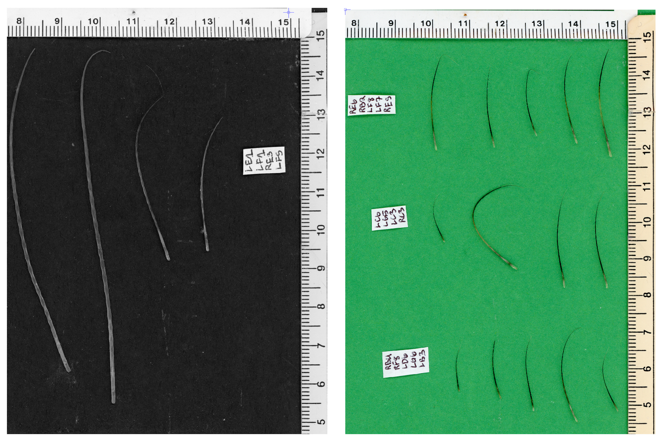
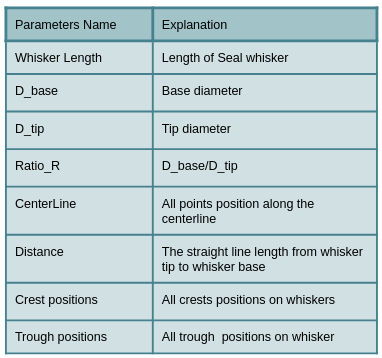
The whiskers images are in two kinds of backgrounds - green and black, as shown on Figure 1. Rulers are placed next to whiskers for the purpose of referencing the size of whiskers. The goal of the project is to extract from seal whiskers parameters (as shown on Table 1) from the original image(Figure 1).
Process
The process of geometric morphometrics of seal whiskers are as shown in Figure 2. There are four main steps: get basic information from the original graph from Figure 1; build a mask from the original image; generate centerline from the mask; and calculate whiskers’ parameters.
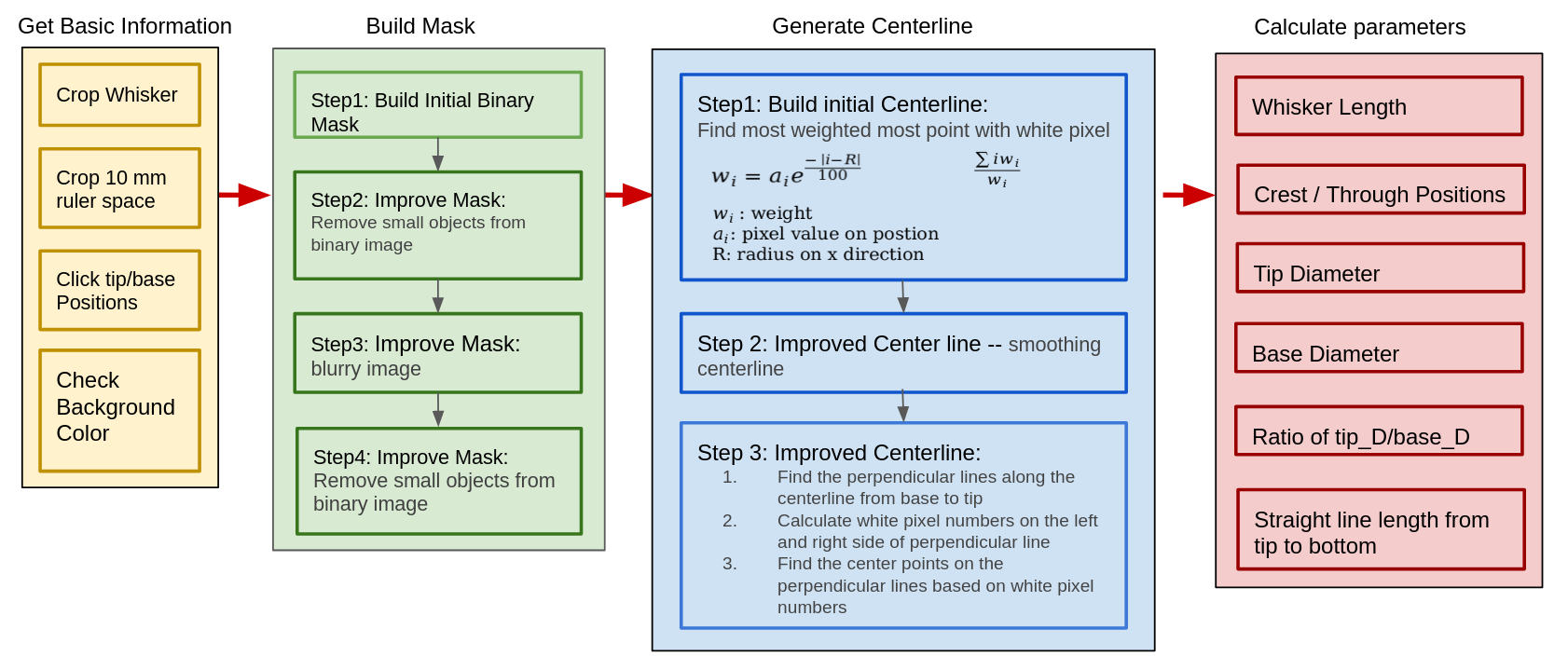
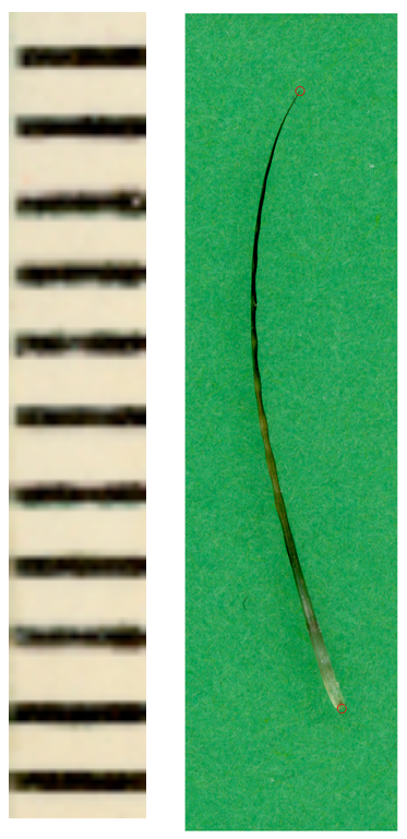
1. Get basic Information
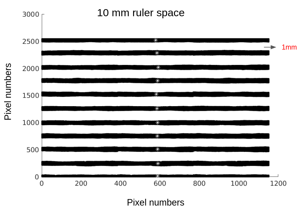
The first step is to get basic whisker information from the original image. As shown in Figure 2, the left graph is a cropped image of a 10 mm ruler, which is used as a reference to estimate whisker size. Also users can pick which whisker they want to extract its parameters, and locate the whisker’s tip and base positions, as shown in the red circle in the right graph.
The original image is on two different backgrounds: black and green. The program on this project is designed to automatically distinguish those two backgrounds by checking the image’s shape. The black background image belongs to a grayscale type, which only has a single color channel, but the green background image belongs to a rgb type, which has three color channels. So it is possible to distinguish between those two backgrounds by checking the number of color channels, then matching the mask building algorithm based on its background.
2. Build Mask
Step 1: Build Initial Mask
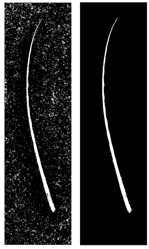
To build an initial mask for a green background image, it checks every pixel’s color value. If it is within the background green color range, then that pixel’s color value would change to 0. Otherwise, it changes to 1. Thereby, it builds the initial mask, as shown in the left side of Figure 3.
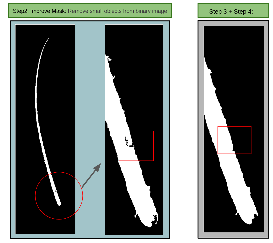
Step2. Improve mask - Remove small objects from binary image
Since the background does not only contain pure green color (left side of Figure 1), there are also some particles in other colors.The initial binary image has many small noise objects besides whiskers. I implement an area filter method to cancel those small objects. If the object area is smaller than the threshold, then I would change its color to its opposite value. Therefore, we can improve the mask by removing small objects as shown on the right side image in Figure 3.
Step3 and Step4. Improve mask - build blurry image
If we look closer at the Step2 image (Figure 4), there are some black objects inside of the whiskers that reach to the background. In order to eliminate it, I blur whiskers’ edges and remove small objects again to build the final mask.
Check whisker edge resolution
To check the resolution of the final mask, I extract its edge and placed it on the original image. It shows the resolution of the final mask is high enough to extract its parameters.
3. Generate Centerline
Step1 & 2 : Build initial Centerline and smooth the centerline
The next step is building the initial center line from the final mask, as shown on Figure 5. It starts from base to tip along the y axis, and it would find the most concentrated point of white pixels on the line (the orange line on figure 5) which is parallel to the x axis for all y values. The equation for finding the most concentrated point is shown on the left side of Figure 5. Then, I smooth the initial centerline to improve it.
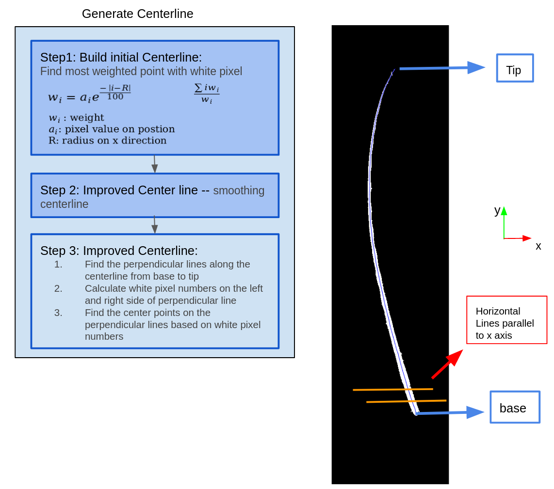
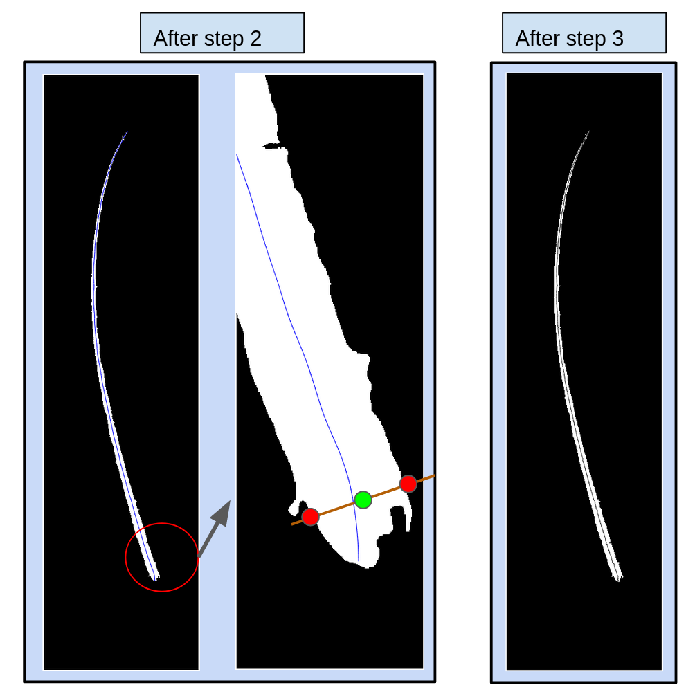
Step3: improve the centerline
After Step 2 of generating the centerline, I improve the centerline by getting every two nearby points on the centerline, and find their linear equation. Then I build a perpendicular line to that linear line. Two white pixel edge points could be found on every perpendicular line. The new centerline points are the middle points of two edge white pixel positions for every perpendicular line. As shown on Figure 6, the middle point in the green color is more centered than the original centerline. Therefore, we could use this method to build a new centerline as shown on the right side of Figure 6.
4. Calculate Parameters
Tip/Base Diameters
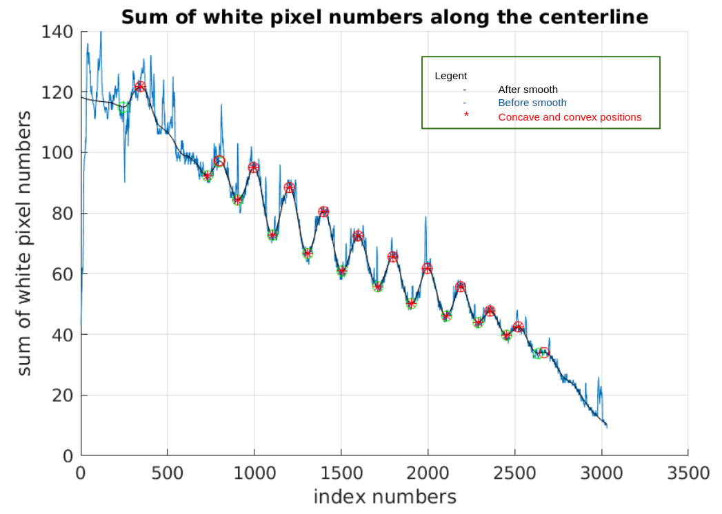
Figure 7 shows the sum of white pixel numbers on the perpendicular lines of the centerline from base to tip. The blue lines are the original white pixel numbers, and the black lines are smoothed from blue lines. Based on the convex and concave points, we can find the crest/trough numbers. The tip diameter is the starting point of the blue line, and the base diameter is the ending point of blue lines.
Crest/Though Positions
As shown on Figure 8, I calculate the white pixel numbers on the left and right side of the centerline, we can find the left and right side white pixel numbers are not the same. It is an interesting result that some whiskers’ crest/trough positions are not symmetric.
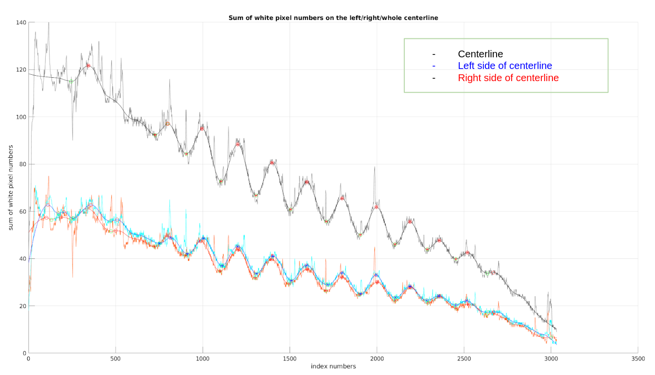
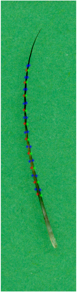
Based on the concave and convex points on Figure 8, I can get crest/trough positions on the left and right side of the centerline. We draw them back to the original image of whiskers as shown on Figure 9. The crests are marked in blue stars, and troughs on the right side are marked in green stars, the troughs on the left side are in blue stars.
Convert pixels number to millimeter
I use the Figure 2 ruler image and place it on a two dimensional graph with pixel numbers. The star points are the middle positions of every bar. Since every two nearby star points are in 1 mm distance, I can convert units from pixel numbers to millimeters.
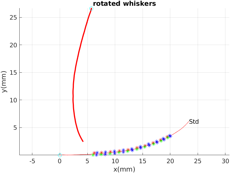
Whisker length
After I convert the unit from pixel to millimeters, I can place whisker’s centerline on 2 dimensional Cartier coordinate. I calculate the length of centerline, and the straight line length from base to tip. Then I rotate the whisker to make it start from the original position and 10 percent of its overall length is a line with the x axis.
code:
The code are published on github:
- https://github.com/luxi-huang/Geometric-Whisker-Parameter-Extraction